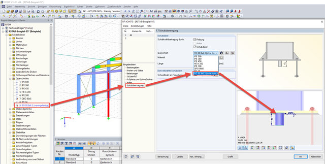
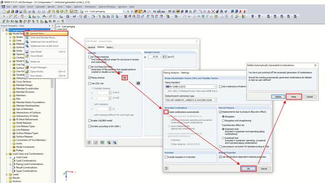
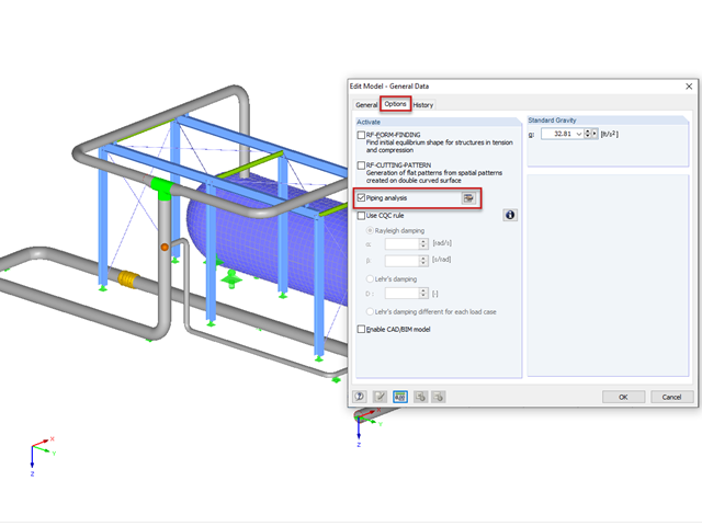
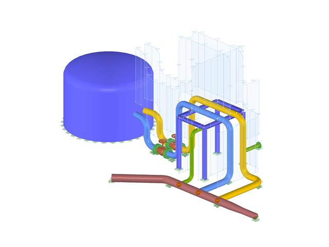
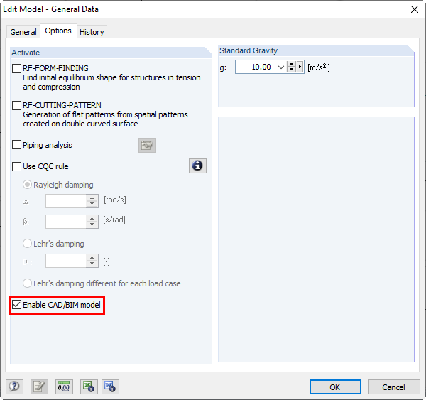
I design pipelines using the RF-PIPING Design add-on module. I have created a new prestress load case and loaded the piping with longitudinal displacement. Is it possible to add this new load case to combinations that are generated automatically?
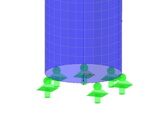
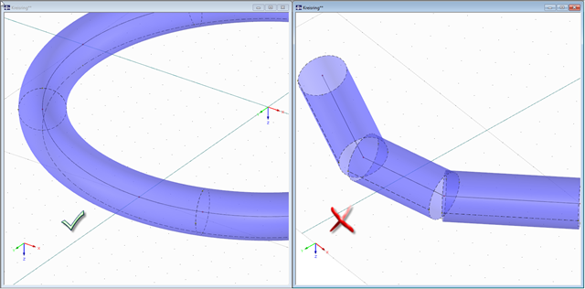
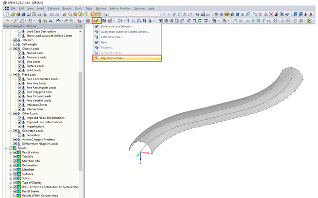
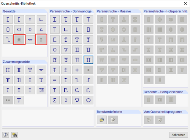
I have generated a surface from a restrained pipe cross-section. Now, an error message appears after the calculation, saying that the nodal loads and nodal supports are not connected. What should I do?
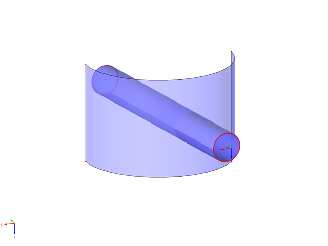
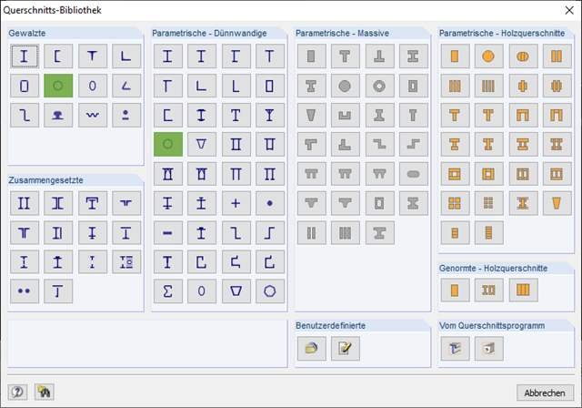
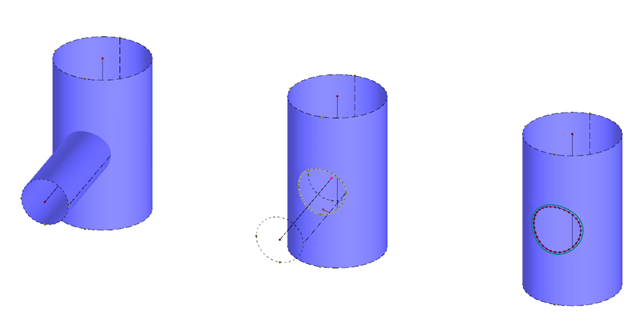
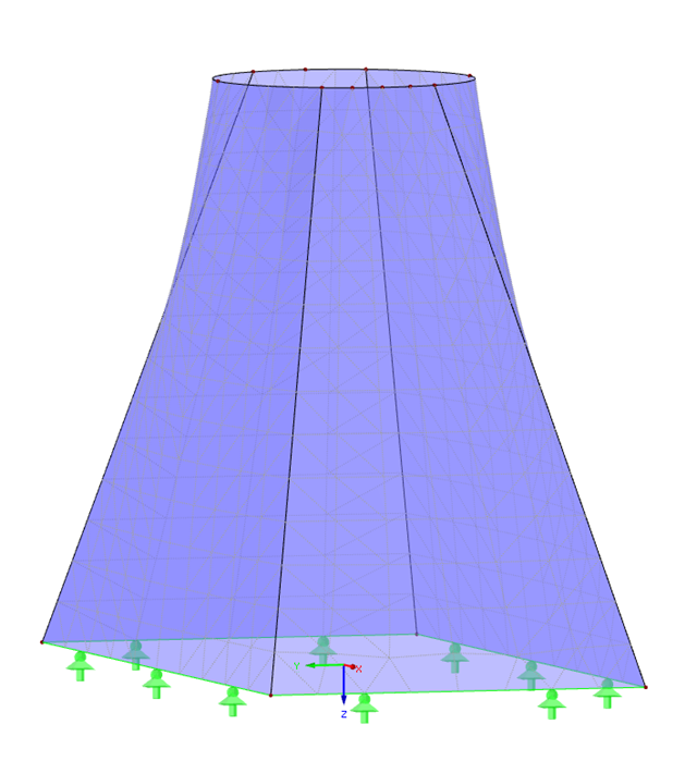
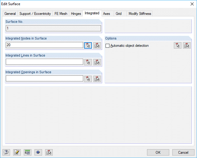
I need to model a curved wall element with some drilled circular holes in the surface. To create these holes in RFEM, I would normally draw a circle in the wall element to create the opening. But how do I draw a circle on a curved surface?
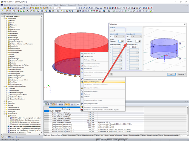
I used the method of intersections to create an opening in a circular cylindrical wall surface.How can I hide these auxiliary surfaces to create an intersection?
In a model, the member end is located on the shell of a pipe. Why is the calculation terminated with a message that the model is not sufficiently supported?
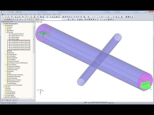
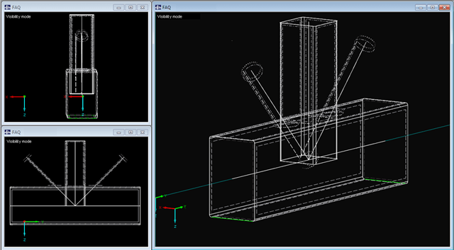
I have a truss node with several rectangular hollow cross-sections connected (modeled as an FE shell structure). To create a realistic connection, it is necessary to remove the surface parts lying in the node from some cross-sections.I achieved this using intersections and deactivating the corresponding surface parts. This significantly slows down work with the model. Is there any other way to generate the node?